Friday 2 September 2016

Differential and Open differential


Differential controls the speed of the left and right wheels on your vehicle.
It allows them to rotate at different speeds while making turns, as the outer wheel path is longer in distance than the inner wheel.


Types of differentials:1)open differentials

                                  2)Limited-slip differentials

                                  3)locking differentials

Open Differential:

Open differentials have a few essential components, illustrated below. The input pinion gear is the gear that is driven from the drivetrain - typically the output shaft from the transmission. It drives the ring gear which, being larger, is what gives that final gear reduction I mentioned. Attached to the ring gear is the cage, containing two captive pinion gears that are intermeshed with the two output pinion gears, one connected to each axle. The captive pinions are free to rotate how they wish.

As the input pinion spins, it meshes with the ring gear. The ring gear spins, spinning the cage and the two captive pinions. When the vehicle is travelling in a straight line, neither drive pinion is trying to spin any differently from the other, so the captive pinions don't spin and the turning of the ring gear is translated directly to both drive pinions. These are connected to the driveshafts to the wheels, so effectively, the ring gear spins the wheels at the same speed that it is turning. When the vehicle starts to turn a corner, one of the wheels is going to want to spin more quickly than the other. At this point, the captive pinions come into play, allowing the two drive pinions to spin at slightly different speeds


How differential works:


references:     www.carbible.com
                       www.learnengineering.com


Wednesday 17 August 2016

Braking system


Brakes is one of the most important element of automobile. There are many types of brakes available in automobile industries. Theses are primary brake, Secondary brakes, vacuum brake, air brake, disk brake, drum brake etc. 

The classification of brakes are as follow. 

According to the purpose:

1. Primary or service brake:

This brake is used when the vehicle is in running condition to stop or slow down the vehicle. This is the main braking system, which is situated in both rear and front wheels of the vehicle. 

2. Secondary brakes:

Secondary brakes, which is also known as parking brake or emergency brake , are used to keep the vehicle stationary. It is generally operated by hand, so also known as hand brake. The main function of this brake, is to keep the vehicle stationary when it is parked. 

According to the construction:

1. Drum brake:

In this type of brakes a drum is attached to the axle hub whereas on the axle casing is mounted a back plate. The back plate is made of pressed steal sheet. It provide support for the expander, anchor and brake shoes. It also protect the drum and shoe assembly from mud and dust. It also known as the torque plate because it absorbed the complete torque reaction of the shoe. Two brake shoe is mounted on back plate with friction linnings. On or two retractor spring are used to seprate brake shoe from drum when the brakes are not applied. The brake shoe are anchored at one end, whereas on the other ends force is applied by means of some brake actuating mechanism which forces the brake shoe against the revolving drum, so the friction force is generated between drum and the shoe and brake applied.

An adjuster is also provided to compensate for wear of friction lining with use. This brakes are widely used in motorcycle and the cars.


2. Disk brake:

Disk brake consists of a cast iron disc bolted to the wheel hub and a stationary housing called caliper. The caliper is connected to some stationary part of the vehicle and it cast in two parts, each part containing a piston. In between each piston and the disc there is a friction pad held in position by retaining pins, springs plates etc. There are arrangements in the caliper for the fluid to enter or leave each housing. There passages are also connected to another one for bleeding.  Each cylinder contains a rubber sealing ring between the cylinder and the piston.


When the brakes are applied, hydraulically actuated piston move the friction pads into contact with the disc, applying equal and opposite forces on the later. On releasing the brakes, the rubber sealing rings act as return springs and retract the pistons and the friction pads away from the disc.
reference:www.mech4study.blogspot.com

Types of brakes

According to the actuation:

1. Mechanical brakes:

In this brakes the brake force is applied mechanically used where we needed small force to braking. This brakes are used in the small vehicle such as in scooters, bikes etc where small braking force is needed. 

2. Hydraulic brakes:

In the hydraulic brakes, brake force is applied by the hydraulic oil. It is one of the most useful and reliable braking system. This brakes is used in most of passenger cars.


3. Electric brakes:

In this braking system magnetic effect of electricity is used to applied the braking force. The braking piston and the disk are connected to the electricity. When we want to apply brake, we start the electricity, which create magnetic effect between brake pad and the disk. So the brake is applied. 


4. Air brakes:


In the air brakes, air pressure is used to the generate the braking force. This braking system is used in heavy load vehicle i.e. trucks, bus etc. 


5. Vacuum brakes:

These brakes used vacuum to apply the force on brake pads. This is the one of the most powerful braking system. This brake is used in the big and heavy vehicle i.e. train, heavy ships etc. 
reference:www.mech4study.blogspot.com

Engine

Engine:An engine is a machine designed to convert one form of energy into mechanical energy.


Classification of engines:

External combustion engine:In this case,cumbustion of fuel takes place outside the cylinder as in case of steam engines where heat of the cumbustion is employed to generate steam which is used to move  a piston in a cylinder.

Internal combustion engine:The internal combustion engine is an engine in which the combustion of a fuel (generally, fossil fuel) occurs with an oxidizer (usually air) in a combustion chamber.In an internal combustion engine the expansion of the high temperature and high pressure gases, which are produced by the combustion,directly applies force to components of the engine, such as the pistons or turbine blades or a nozzle, and by moving it over a distance, generates useful mechanical energy.


ref:www.mech4study.blogspot.com


engine and its components

common parts of ic engine are
1)cylinder block
2)cylinderhead
3)piston
4)piston rings
5)gudgeon pin
6)connecting rod
7)crank
8)crank shaft
9)engine bearing
10)crank case
11)flywheel
12)governor
13)cam shaft
14)valve and value operating mechanism
15)rocker arms
16)oil pan
17)manifold
18)rubber grommets
19)Head gasket
20)spark plug

1. Cylinder block

Cylinder is the main body of IC engine. Cylinder is a part in which the intake of fuel, compression of fuel and burning of fuel take place. The main function of cylinder is to guide the piston. It is in direct contact with the products of combustion so it must be cooled. For cooling of cylinder a water jacket (for liquid cooling used in most of cars) or fin (for air cooling used in most of bikes) are situated at the outer side of cylinder. At the upper end of cylinder, cylinder head and at the bottom end crank case is bolted. The upper side of cylinder is consists of a combustion chamber where fuel burns. To handle all this pressure and temperature generated by combustion of fuel, cylinder material should have high compressive strength. So it is made by high grade cast iron. It is made by casting and usually cast in one piece.

Main Parts of an Internal Combustion Engine (cylinder block)

2. Cylinder head

The top end of cylinder is closed by means of removable cylinder head. There are two holes or ports at the cylinder head, one for intake of fuel and other for exhaust. Both the intake and exhaust ports are closed by the two valves known as inlet and exhaust valve. The inlet valve, exhaust valve, spark plug, injector etc. are bolted on the cylinder head. The main function of cylinder head is to seal the cylinder block and not to permit entry and exit of gases on cover head valve engine. Cylinder head is usually made by cast iron or aluminum. It is made by casting or forging and usually in one piece.

Main Parts of an Internal Combustion Engine (cylinder head)

3. Piston

A piston is fitted to each cylinder as a face to receive gas pressure and transmit the thrust to the connecting rod. It is the prime mover in the engine. The main function of piston is to give tight seal to the cylinder through bore and slide freely inside of cylinder. Piston should be light and sufficient strong to handle the gas pressure generated by combustion of fuel. So the piston is made by aluminum alloy and sometimes it is made by cast iron because light alloy piston expands more than cast iron so they need more clearances to the bore.

Main Parts of an Internal Combustion Engine (piston)

4. Piston rings

A piston must be a fairly loose fit in the cylinder so it can move freely inside the cylinder. If the piston is too tight fit, it would expand as it got hot and might stick tight in the cylinder and if it is too loose it would leaks the vapor pressure. To provide a good sealing fit and less friction resistance between the piston and cylinder, pistons are equipped with piston rings. These rings are fitted in grooves which have been cut in the piston. They are split at one end so they can expand or slipped over the end of piston.  A small two stroke engine has two piston rings to provide good sealing but in a four stroke engine has an extra ring which is known as oil ring. Piston rings are made of cast iron of fine grain and high elastic material which is not affected by the working heat. Sometimes it is made by alloy spring steel. 

Main Parts of an Internal Combustion Engine (piston rings)

5. Connecting rod

Connecting rod connects the piston to crankshaft and transmits the motion and thrust of piston to crankshaft. It converts the reciprocating motion of the piston into rotary motion of crankshaft. There are two end of connecting rod one is known as big end and other as small end. Big end is connected to the crankshaft and the small end is connected to the piston by use of piston pin. The connecting rods are made of nickel, chrome, and chrome vanadium steels. For small engines the material may be aluminum. 

Main Parts of an Internal Combustion Engine (connecting rod)

6. Crankshaft

The crankshaft of an internal combustion engine receives the efforts or thrust supplied by piston to the connecting rod and converts the reciprocating motion of piston into rotary motion of crankshaft. The crankshaft mounts in bearing so it can rotate freely. The shape and size of crankshaft depends on the number and arrangement of cylinders. It is usually made by steel forging, but some makers use special types of cast-iron such as spheroidal graphitic or nickel alloy castings which are cheaper to produce and have good service life. 

Main Parts of an Internal Combustion Engine (crankshaft)

7. Engine bearing

Everywhere there is rotary action in the engine, bearings need. Bearings are used to support the moving parts.  The crankshaft is supported by bearing. The connecting rod big end is attached to the crank pin on the crank of the crankshaft by a bearing. A piston pin at the rod small end is used to attach the rod to the piston, also rides in bearings. The main function of bearings is to reduce friction between these moving parts. In an IC engine sliding and rolling types of bearing used. The sliding type bearing which are sometime called bush is use to attach the connecting rod to the piston and crankshaft. They are split in order to permit their assembly into the engine. The rolling and ball bearing is used to support crankshaft so it can rotate freely. The typical bearing half is made of steel or bronze back to which a lining of relatively soft bearing material is applied. 

Main Parts of an Internal Combustion Engine (engine bearing)

8. Crankcase

The main body of the engine to which the cylinder are attached and which contains the crankshaft and crankshaft bearing is called crankcase. It serves as the lubricating system too and sometime it is called oil sump. All the oil for lubrication is placed in it. 


Main Parts of an Internal Combustion Engine (crankcase)

9. Valves

To control the inlet and exhaust of internal combustion engine, valves are used. The number of valves in an engine depends on the number of cylinders. Two valves are used for each cylinder one for inlet of air-fuel mixture inside the cylinder and other for exhaust of combustion gases. The valves are fitted in the port at the cylinder head by use of strong spring. This spring keep them closed. Both valves usually open inwards. 

Main Parts of an Internal Combustion Engine (valves)

10. Spark plug

It is used in spark ignition engine. The main function of a spark plug is to conduct the high potential from the ignition system into the combustion chamber to ignite the compressed air fuel mixture. It is fitted on cylinder head. The spark plug consists of a metal shell having two electrodes which are insulated from each other with an air gap. When high potential current supply to spark plug it jumping from the supply electrode and produces the necessary spark.


Main Parts of an Internal Combustion Engine (spark plug)

11. Injector

Injector is usually used in compression ignition engine. It sprays the fuel into combustion chamber at the end of compression stroke. It is fitted on cylinder head. 

Main Parts of an Internal Combustion Engine (injector)

12. Manifold

The main function of manifold is to supply the air fuel mixture and collects the exhaust gases equally form all cylinder. In an internal combustion engine two manifold are used, one for intake and other for exhaust. They are usually made by aluminum alloy. 

Main Parts of an Internal Combustion Engine (manifold)

13. Camshaft

Camshaft is used in IC engine to control the opening and closing of valves at proper timing. For proper engine output inlet valve should open at the end of exhaust stroke and closed at the end of intake stroke. So to regulate its timing, a cam is use which is oval in shape and it exerts a pressure on the valve to open and release to close. It is drive by the timing belt which drives by crankshaft. It is placed at the top or at the bottom of cylinder.

Main Parts of an Internal Combustion Engine (camshaft)

14. Gudgeon pin or piston pin

These are hardened steel parallel spindles fitted through the piston bosses and the small end bushes or eyes to allow the connecting rods to swivel. It connects the piston to connecting rod. It is made hollow for lightness.

Main Parts of an Internal Combustion Engine (piston pin)

15. Pushrod

Pushrod is used when the camshaft is situated at the bottom end of cylinder.  It carries the camshaft motion to the valves which are situated at the cylinder head. 

Main Parts of an Internal Combustion Engine (pushrod)

16. Flywheel

A flywheel is secured on the crankshaft. The main function of flywheel is to rotate the shaft during preparatory stroke. It also makes crankshaft rotation more uniform. 


Main Parts of an Internal Combustion Engine (flywheel)
- See more at: http://www.mech4study.com

Classification of ic engines

Types of I.C. Engine


I.C. engine is widely used in automobile industries so it is also known as automobile engine. An automobile engine may be classified in many manners. Today I am going to tell you some important classification of an automobile engine.


According to number of stroke:

1. Two stroke engine

In a two stroke engine a piston moves one time up and down inside the cylinder and complete one crankshaft revolution during single time of fuel burn. This type of engine has high torque compare to four stroke engine. These are generally used in scooters, pumping sets etc.

2. Four stroke engine

In a four stroke engine piston moves two times up and down inside the cylinder and complete two crankshaft revolutions during single time of fuel burn. This type of engines has high average compare to two stroke engine. These are generally used in bikes, cars, truck etc.

According to design of engine:

1. Reciprocating engine (piston engine)

In reciprocating engine the pressure force generate by combustion of fuel exerted on the piston (A device which free to move in reciprocation inside the cylinder). So the piston starts reciprocating motion (too and fro motion).  This reciprocating motion converts into rotary motion by use of crank shaft. So the crank shaft starts to rotate and rotate the wheels of vehicle. These are generally used in all automobile.

2. Rotary engine (Wankel engine)

In rotary engine there is a rotor which frees to rotate. The pressure force generate by burning of fuel is exerted on this rotor so the rotor rotate and starts to rotate the wheels of vehicle. This engine is developed by Wankel in 1957. This engine is not used in automobile in present days.

According to fuel used:

1. Diesel engine

These engines use diesel as the fuel. These are used in trucks, buses, cars etc.

2. Petrol engine

These engines use petrol as the fuel. These are used in bikes, sport cars, luxury cars etc.

3. Gas engine

These engines use CNG and LPG as the fuel. These are used in some light motor vehicles.

4. Electric engine

It is eco-friendly engine. It doesn’t use any fuel to burn. It uses electric energy to rotate wheel.

According to method of ignition:

1. Compression ignition engine

In these types of engines, there is no extra equipment to burn the fuel. In these engines burning of fuel starts due to temperature rise during compression of air. So it is known as compression ignition engine.

2. Spark ignition engine

In these types of engines, ignition of fuel start by the spark, generate inside the cylinder by some extra equipment. So it is known as spark ignition engine.

According to number of cylinder:

1. Single cylinder engine

In this type of engines have only one cylinder and one piston connected to the crank shaft.

2. Multi-cylinder engine

In this type of engines have more than one cylinder and piston connected to the crank shaft.

According to arrangement of cylinder:

1. In-line engine

In this type of engines, cylinders are positioned in a straight line one behind the other along the length of the crankshaft.
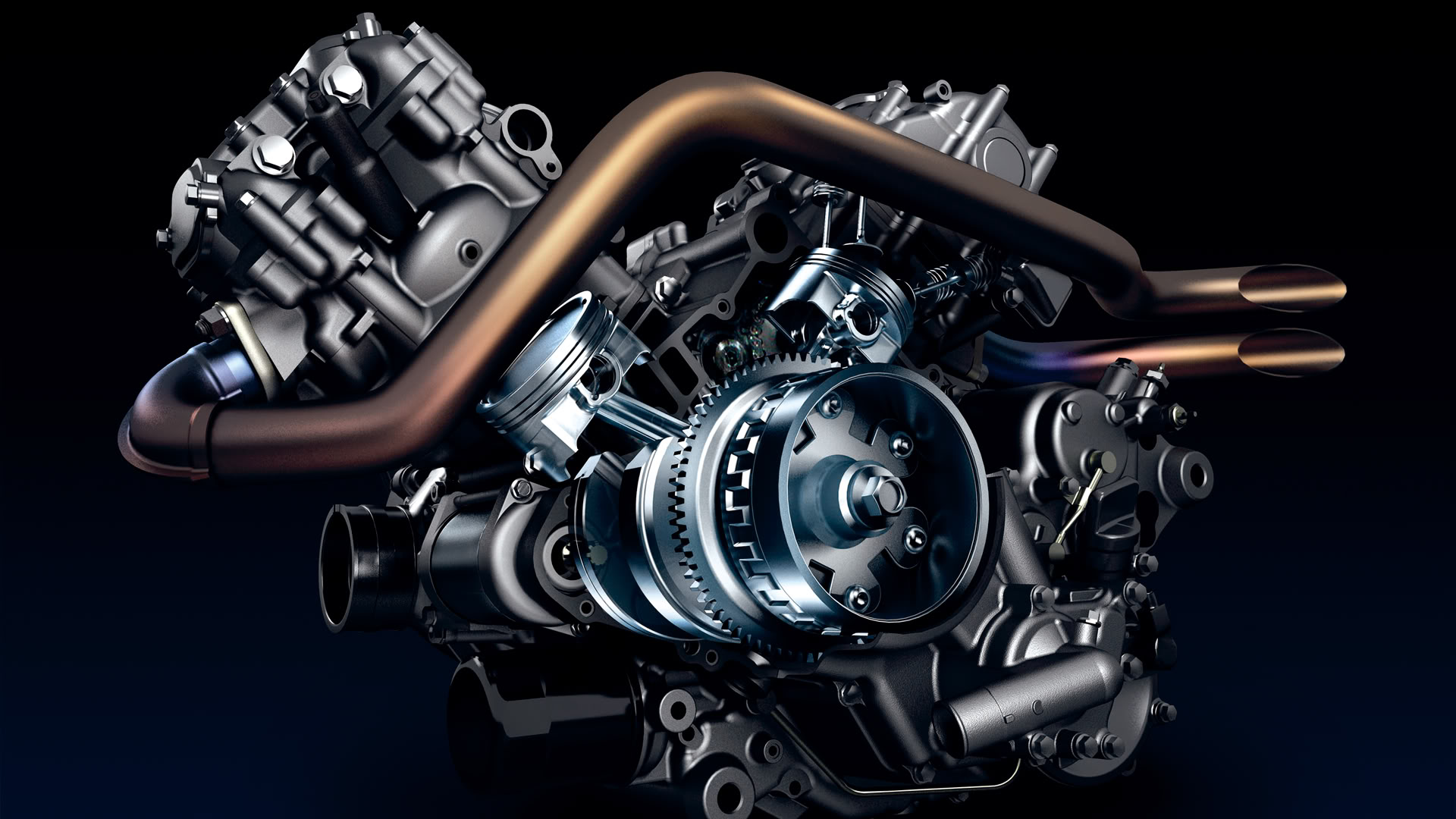
What is Engine? What are Main Types of Engine?

2. V-type engine

An engine with two cylinder banks inclined at an angle to each other and with one crankshaft known as V-type engine.

What is Engine? What are Main Types of Engine?

3. Opposed cylinder engine

An engine with two cylinders banks opposite to each other on a single crankshaft (V-type engine with 180angle between banks).

What is Engine? What are Main Types of Engine?

4. W-type engine

An engine same as V-type engine except with three banks of cylinders on the same crankshaft known as W-type engine.

5. Opposite piston engine

In this type of engine there are two pistons in each cylinder with the combustion chamber in the center between the pistons. In this engine a single combustion process causes two power strokes, at the same time.

What is Engine? What are Main Types of Engine?

6. Radial engine

It is an engine with pistons positioned in circular plane around the central crankshaft. The connecting rods of pistons are connected to a master rod which, in turn, connected to the crankshaft.

What is Engine? What are Main Types of Engine?
ref: http://www.mech4study.com/