Wednesday, 17 August 2016

Classification of ic engines

Types of I.C. Engine


I.C. engine is widely used in automobile industries so it is also known as automobile engine. An automobile engine may be classified in many manners. Today I am going to tell you some important classification of an automobile engine.


According to number of stroke:

1. Two stroke engine

In a two stroke engine a piston moves one time up and down inside the cylinder and complete one crankshaft revolution during single time of fuel burn. This type of engine has high torque compare to four stroke engine. These are generally used in scooters, pumping sets etc.

2. Four stroke engine

In a four stroke engine piston moves two times up and down inside the cylinder and complete two crankshaft revolutions during single time of fuel burn. This type of engines has high average compare to two stroke engine. These are generally used in bikes, cars, truck etc.

According to design of engine:

1. Reciprocating engine (piston engine)

In reciprocating engine the pressure force generate by combustion of fuel exerted on the piston (A device which free to move in reciprocation inside the cylinder). So the piston starts reciprocating motion (too and fro motion).  This reciprocating motion converts into rotary motion by use of crank shaft. So the crank shaft starts to rotate and rotate the wheels of vehicle. These are generally used in all automobile.

2. Rotary engine (Wankel engine)

In rotary engine there is a rotor which frees to rotate. The pressure force generate by burning of fuel is exerted on this rotor so the rotor rotate and starts to rotate the wheels of vehicle. This engine is developed by Wankel in 1957. This engine is not used in automobile in present days.

According to fuel used:

1. Diesel engine

These engines use diesel as the fuel. These are used in trucks, buses, cars etc.

2. Petrol engine

These engines use petrol as the fuel. These are used in bikes, sport cars, luxury cars etc.

3. Gas engine

These engines use CNG and LPG as the fuel. These are used in some light motor vehicles.

4. Electric engine

It is eco-friendly engine. It doesn’t use any fuel to burn. It uses electric energy to rotate wheel.

According to method of ignition:

1. Compression ignition engine

In these types of engines, there is no extra equipment to burn the fuel. In these engines burning of fuel starts due to temperature rise during compression of air. So it is known as compression ignition engine.

2. Spark ignition engine

In these types of engines, ignition of fuel start by the spark, generate inside the cylinder by some extra equipment. So it is known as spark ignition engine.

According to number of cylinder:

1. Single cylinder engine

In this type of engines have only one cylinder and one piston connected to the crank shaft.

2. Multi-cylinder engine

In this type of engines have more than one cylinder and piston connected to the crank shaft.

According to arrangement of cylinder:

1. In-line engine

In this type of engines, cylinders are positioned in a straight line one behind the other along the length of the crankshaft.

What is Engine? What are Main Types of Engine?

2. V-type engine

An engine with two cylinder banks inclined at an angle to each other and with one crankshaft known as V-type engine.

What is Engine? What are Main Types of Engine?

3. Opposed cylinder engine

An engine with two cylinders banks opposite to each other on a single crankshaft (V-type engine with 180o angle between banks).

What is Engine? What are Main Types of Engine?

4. W-type engine

An engine same as V-type engine except with three banks of cylinders on the same crankshaft known as W-type engine.

5. Opposite piston engine

In this type of engine there are two pistons in each cylinder with the combustion chamber in the center between the pistons. In this engine a single combustion process causes two power strokes, at the same time.

What is Engine? What are Main Types of Engine?

6. Radial engine

It is an engine with pistons positioned in circular plane around the central crankshaft. The connecting rods of pistons are connected to a master rod which, in turn, connected to the crankshaft.

What is Engine? What are Main Types of Engine?
ref: http://www.mech4study.com/

Turbo charger and super charger

Supercharger and turbocharger works on same principle i.e. by using compressor. Turbocharger and supercharger both compresses the air and forces this compressed air into the engine cylinder. According to the air, large amount of fuel is injected into the cylinder, which produces more power. It is the basic principle of both turbocharger and supercharger. 

1)Supercharger is an air compressor which is used to increase the power of an engine. Basically supercharger is a rotary compressor which is driven by  the crankshaft through a belt drive. This compressor is connected at the inlet manifold of the engine. As the engine rotate it rotate the supercharger which forces compressed air into cylinder.
Difference Between Supercharger vs Turbocharger  

2)Turbocharger is basically a combination of a turbine and a rotary compressor. The turbine is connected to the compressor and driven by the hot exhaust gases of the engine. So a turbocharge is a compressor which is driven by exhaust gases of engine which forces the compressed gases into the cylinder.

Difference Between Supercharger vs Turbocharger
ref:www.mech4study.blogspot.com


Types of gears

  1. Spur Gear
  2. Helical Gear
  3. Herringbone Gear
  4. Bevel Gear
  5. Worm Gear
  6. Rack and Pinion
  7. Internal and External Gear
  8. Face Gear
  9. Sprcokets
  1. Spur Gear:Spur gears have straight teeth and are parallel to the axis of the wheel. Spur gears are the most common type of gears. The advantages of spur gears are their simplicity in design, economy of manufacture and maintenance, and absence of end thrust. They impose only radial loads on the bearings.Spur gears are known as slow speed gears. If noise is not a serious design problem, spur gears can be used at almost any speed.
  2. Helical Gear:Helical gears have their teeth inclined to the axis of the shafts in the form of a helix, hence the name helical gears.

    These gears are usually thought of as high speed gears. Helical gears can take higher loads than similarly sized spur gears. The motion of helical gears is smoother and quieter than the motion of spur gears.

    Single helical gears impose both radial loads and thrust loads on their bearings and so require the use of thrust bearings. The angle of the helix on both the gear and the must be same in magnitude but opposite in direction, i.e., a right hand pinion meshes with a left hand gear.
  3. Herringbone Gear:Herringbone gears resemble two helical gears that have been placed side by side. They are often referred to as "double helicals". In the double helical gears arrangement, the thrusts are counter-balanced. In such double helical gears there is no thrust loading on the bearings.
  4. Spiral Bevel gears: In these Spiral Bevel gears, the teeth are oblique. Spiral Bevel gears are quieter and can take up more load as compared to straight bevel gears.
  5.          Worm Gear- Worm gears are used to transmit power at 90° and where high reductions are required. The axes of worm gears shafts cross in space. The shafts of worm gears lie in parallel planes and may be skewed at any angle between zero and a right angle.In worm gears, one gear has screw threads. Due to this, worm gears are quiet, vibration free and give a smooth output.Worm gears and worm gear shafts are almost invariably at right angles.
  6.           Rack and Pinion- A rack is a toothed bar or rod that can be thought of as a sector gear with an infinitely large radius of curvature. Torque can be converted to linear force by meshing a rack with a pinion: the pinion turns; the rack moves in a straight line. Such a mechanism is used in automobiles to convert the rotation of the steering wheel into the left-to-right motion of the tie rod(s). Racks also feature in the theory of gear geometry, where, for instance, the tooth shape of an interchangeable set of gears may be specified for the rack (infinite radius), and the tooth shapes for gears of particular actual radii then derived from that. The rack and pinion gear type is employed in a rack railway.
  7.    Face Gears- Face gears transmit power at (usually) right angles in a circular motion. Face gears are not very common in industrial application.
  8. Sprockets-Sprockets are used to run chains or belts. They are typically used in conveyor systems.
    ref:www.mech4study.blogspot.com

Types of clutches

Single Plate Clutch:
The diagram shows the pressure plate pulled back by the release levers against the compression springs; so that the friction linings on the clutch plate are free of flywheel and pressure plate. The flywheel rotates without driving the clutch plate and hence the shaft.
When the pressure of the thrust race is released the compression springs are free to move the pressure plate to the left bringing it in contact with the clutch plate.
The pressure plate moves to the left, sliding the clutch plate on its splined hub, along the driven shaft until the friction lining touches the flywheel.
The compression springs now cause the linings to be gripped between the pressure plate and the flywheel and the friction between the linings and flywheel and pressure plate causes the clutch plate to revolve, turning the driven shaft.

Multi plate clutch:
When a great amount of torque is to be transmitted, instead of single plate a number of friction plates are employed. This increases the number of mating friction surfaces, hence it is called multiplate clutch.
These clutches are used in heavy commercial vehicles, racing cars and motor cycles for transmitting high torque


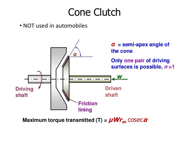
cone clutch:It consists of a flywheel and a cone mounted on driving and driven shafts respectively. The shape of the side of the flywheel facing the cone is as to accommodate the cone readily when the clutch is engaged. The surfaces of contact are lined with the friction lining (Asbestos, leather etc.). The cone can be disengaged from flywheel by mechanism which operates in the groove of the cone.
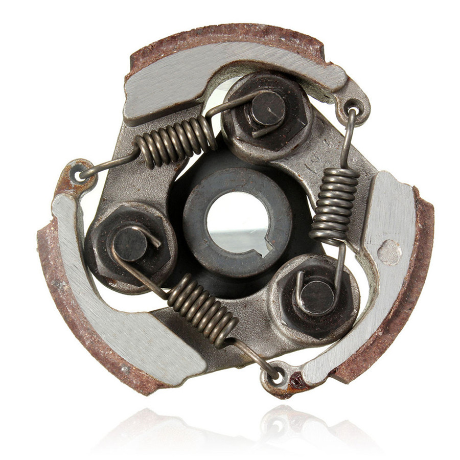
centrifugal clutch:A centrifugal clutch is a clutch that uses centrifugal force to connect two concentric shafts, with the driving shaft nested inside the driven shaft. It engages more at higher speeds.

The input of the clutch is connected to the engine crankshaft while the output may drive a shaft, chain, or belt. As engine revolutions per minute increase, weighted arms in the clutch swing outward and force the clutch to engage. The most common types have friction pads or shoes radially mounted that engage the inside of the rim of a housing. On the center shaft there are an assorted number of extension springs, which connect to a clutch shoe. When the central shaft spins fast enough, the springs extend causing the clutch shoes to engage the friction face. It can be compared to a drum brake in reverse.


ref:www.mech4study.blogspot.com


Clutch and its compnents

CLUTCH:A clutch is a mechanical device that engages and disengages the power transmission, especially from driving shaft to driven shaft. It is located between flywheel and gearbox.


1)Primary components
   Flywheel
   Clutch disc
   Pressure plate
   Release (Throw out) bearing

2)Secondary components 
   Pilot bearing 
   Release fork 
   Slave cylinder


Transmission system

Transmission system:Transmission is the mechanism that transmits the power from the engine crankshaft to the wheels, providing the variable speed and torque at the road wheels as per the requirement

Types of transmission systems:
1)Manual Transmission
2)Fully-Automatic Transmission
3)Semi-Automatic Transmission
4)Continuously Variable Transmission
1)Manual Transmission:In case of the manual transmission system, the vehicle is driven with the assistance of gearshift and clutch. The other components, which are used in this process, are flywheel, pressure plate and ring gears.


2)Automatic transmission:In case of the automatic transmission system, the gears are changed automatically corresponding with the vehicle's speed. The basic components essential for this process are modulator, torque converter, planetary gears, governor, computer, seals and hydraulic designs.
3)continuous variable transimmision:The most basic CVT has two variable pulleys and either a steel-core rubber pull-belt or a steel alloy push-belt. One pulley is connected to the flywheel and the other to the gearbox output shaft. The belt loops around between the two. On simple scooter-type CVTs, the pulleys change geometry simply by rotational forces - the faster the engine pulley spins, the more it closes up and the faster the output pulley spins, the more it opens out. In automotive applications, the geometry of the pulley is governed by a hydraulic piston connected to the ECU. The pulley itself is basically a splined shaft with a pair of sliding conical wedges on it (called 'Sheaves').


www.carbible.com


Types of suspension system part2

SOLID-AXLE, LEAF-SPRING


The drive axle is clamped to the leaf springs and the shock absorbers normally bolt directly to the axle. The ends of the leaf springs are attached directly to the chassis, as are the tops of the shock absorbers. Simple, not particularly elegant, but cheap. The main drawback with this arrangement is the lack of lateral location for the axle, meaning it has a lot of side-to-side slop in it.

Leaf springs:

The spring consist of a number of leaves called blades. The blades vary in length and connected together as shown in the figure. These springs based on the theory of beam of uniform strength.

This spring is mounted on the axle by the U bolt and the one end of spring is mounted on the frame and other is connected with a shackle which allow to change in length between eye of spring when the vehicle come across projection of road and upward movement of wheel.
When there is wide range of loading on vehicle helper spring is also provided with the leaf spring which increase the weight loading capacity of vehicle.


Types of leaf springs are 1)elliptic:
                                         2)semi-elliptic:


                                            3) quater elliptic:


                                             4)Three quater elliptic:
SOLID-AXLE, COIL-SPRING

The basic idea is the same, but the leaf springs have been removed in favour of either 'coil-over-oil' spring and shock combos, or as shown here, separate coil springs and shock absorbers. Because the leaf springs have been removed, the axle now needs to have lateral support from a pair control arms. The front ends of these are attached to the chassis, the rear ends to the axle.
ref:www.carbible.com