Showing posts with label steering system. Show all posts

Tuesday, 16 August 2016

Steering system

The steering system converts the rotation of the steering wheel into a swivelling movement of the road wheels in such a way that the steering-wheel rim turns a long way to move the road wheels a short way.

The follwing are the components of steeering system
1. Steering Wheel
2. Steering column or shaft
3. Steering Gear
4. Drop Arm or Pitman Arm
5. Drag Link
6. Steering Arm
7. Track-Arms
8. Track Rod or Tie-Rod
9. Adjusting Screws

Types of Steering Gear Boxes:
1. Worm and Wheel Steering Gear.
2. Worm and Roller Steering Gear.
3. Re-circulating Ball type Steering Gear.
4. Rack and Pinion type Steering Gear.
5. Cam and Roller Gear type Steering Gear.
6. Cam and Peg Steering Gear.
7. Cam and Double lever Steering Gear.

8. Worm and Sector Type Steering Gear.

ref:www.carbible.com

steering gear boxes

1.Worm and Wheel Type:
 This type of steering gear has a square cut screw
threads at the end of the steering column; which forms a worm, at the end of
it a worm wheel is fitted and works rigidly with it. Generally covered shaft is
used for the worm wheel. The worm wheel can be turned to a new position
the drop arm can be readjusted to the correct working position.
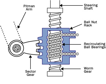
2. Re-circulating Ball Type:
In this type of gear box the endless chain of balls
are provided between the worm and nut members. The nut form a ring of
rack having an axial movement. So that the sector on the rocker shaft racks,
the balls roll continuously between the worm and nut. Being provided with
return chambers at the ends of the worm. This method reduces friction
between worm and nut members. This type of steering gear is used for heavy
vehicles.
3. Rack and Pinion Type: This is common manual type of steering gear box
is used in most of the vehicles. In this type of steering a pinion is provided the
bottom end of the steering column. The teeth of the pinion wheel in mesh
with corresponding teeth provided on the rack, the end of which areconnected to the stub axle through the rod. The rotating motion of the pinion operates the rack  direction which in turn operates the stub axle.

4. Cam and Lever Type: The cam and lever steering uses one or two lever
studs fitted in taper roller bearing. When the worm in the form of helical
groove rotates the stub axle and it also rotates along with it. This imports a
turning motion to the drop arm shaft.
5. Worm and Sector Type: In this type the worm on the end of the steering
shaft meshes with a sector mounted on a sector shaft. When the worm is
rotated by rotation of the steering wheel, the sector also turn rotating the
sector shaft. Its motion is transmitted to the wheel through the linkage. The
sector shaft is attached to the drop arm or pitmen arm.
Power


Steering Mechanism:

Steering Mechanism: There are two types of steering gear mechanisms
1. Davis Steering gear 2. Ackermann Steering gear

1. Davis Steering gear :The Davis Steering gear has sliding pair, it has more
friction than the turning pair, there fore the Davis Steering Gear wear out
earlier and become inaccurate after certain time. This type is mathematically
Accurate.
Tan á = b/2l Where b= AB = distance between the pivots of front axle.
l=wheel base
2. Ackermann Steering System: It has only turning pair. It is not
mathematically accurate except in three positions. The track arms are made
inclined so that if the axles are extended they will meet on the longitudinal
axis of the car near rear axle. This system is called ackermann steering.
ref:www.carbible.com

Steering Geomentry

The steering Geometry includes
1. Caster angle
2. Camber angle
3. King-pin inclination
4. toe-in
5. toe-out etc.,
Caster Angle: This is the angle between backward or forward tilting of the
king pin from the vertical axis at the top. This is about 2º to 4º. The backward
tilt is called as positive caster. The forward tilt is called negative caster.
Camber: The angle between wheel axis to the vertical line at the top is
called camber angle. It is approximately ½º to 2º.

King-pin inclination: It is the angle between vertical line to the king pin axis.
The inclination tends to keep wheels straight ahead and make the wheels to
get return to the straight position after completion of a turn. The inclination is
normally kept 7º to 8º.
Toe-in: It is the amount in minimum at the front part of the wheel points
inwards approximately 3 to 5 mm. It prevents side slipping excessive tyre
wear, proper rolling of front wheels and steering stability.

Toe-out: 
 The slight forward divergence that the front wheels of an automobileundergo during forward motion, especially in turns.