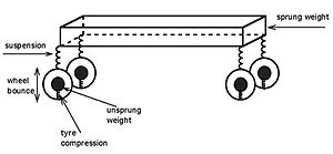
Tuesday 16 August 2016

Types of supension system part1

 1)Dependent Suspension - It is a type of suspension in which left and right suspension are linked together and disturbance on one side is transferred to other side.
    Independent Suspension - It is a type of suspension in which left and right suspension are not linked together and disturbance on one side is not transferred to other side.
Independent suspension is classified into
                                                                                                 1).MacPherson Strut
                                                                                                 2).Double Wishbone

 1).MacPherson Strut: The MacPherson strut combines a shock absorber and a coil spring into a single unit. This provides a more compact and lighter suspension system that can be used for front-wheel drive vehicles.


 2).Double Wishbone:This is classified into

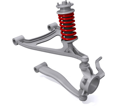
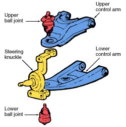
  a) COIL SPRING TYPE 1:
    This is a type of double-A or double wishbone suspension. The wheel spindles are supported by an upper and lower 'A' shaped arm.In this type, the lower arm carries most of the load. If you look head-on at this type of system, what you'll find is that it's a very parallelogram system that allows the spindles to travel vertically up and down. When they do this, they also have a slight side-to-side motion caused by the arc that the wishbones describe around their pivot points. This side-to-side motion is known as scrub.Unless the links are infinitely long the scrub motion is always present. There are two other types of motion of the wheel relative to the body when the suspension articulates.


 b) COIL SPRING TYPE 2:This is also a type of double-A arm suspension although the lower arm in these systems can sometimes be replaced with a single solid arm . The only real difference between this and the previous system mentioned above is that the spring/shock combo is moved from between the arms to above the upper arm. This transfers the load-bearing capability of the suspension almost entirely to the upper arm and the spring mounts. The lower arm in this instance becomes a control arm

c)Multi link suspension:The basic principle of it is the same, but instead of solid upper and lower wishbones, each 'arm' of the wishbone is a separate item. These are joined at the top and bottom of the spindle thus forming the wishbone shape. The super-weird thing about this is that as the spindle turns for steering, it alters the geometry of the suspension by torquing all four suspension arms. 

    There are a lot of variations on this theme appearing at the moment, with huge differences in the numbers and complexities of joints, numbers of arms, positioning of the parts etc. but they are all fundamentally the same.
d)trailing arm suspension:The trailing arm system is literally that - a shaped suspension arm is joined at the front to the chassis, allowing the rear to swing up and down. Pairs of these become twin-trailing-arm systems and work on exactly the same principle as the double wishbones in the systems described above. The difference is that instead of the arms sticking out from the side of the chassis, they travel back parallel to it. This is an older system not used so much any more because of the space it takes up.

e)twin I beam suspension:This is a combination of trailing arm suspension and solid beam axle suspension. Only in this case the beam is split in two and mounted offset from the centre of the chassis, one section for each side of the suspension. The trailing arms are actually (technically) leading arms and the steering gear is mounted in front of the suspension setup. 
ref:www.carbible.com


Suspension system

 Suspension system : The automobile frame and body are mounted on the front and
rear axle not directly but through the springs and shock absorbers. The
assembly of parts, which perform the isolation of parts from the road shocks,
may be in the forms of bounce, pitch and roll is called suspension system.
Basic parts of suspension system:
1)control arm: Movable lever that fastens the steering knuckle to the vehicl body or frame.
2)Steering knuckle:Provides a spindle or bearing support for the wheel hub,bearings and wheel assembly.

3)Ball joints:Swivel joints that allow control arm and steering knuckle to move up and down and side to side
4)Springs:Supports the weight of the vehicle;permits the control arm and wheel to move up and down.
5)Shock absorbers(or)dampers:Keeps the suspension from coutinuing to bounce after spring compression and extension.
6)control arm bushings:Sleeves that allow the control arm to swing up and down on the frame.

Suspension Terminology

1)Sprung Weight: It is weight of all the parts supported by the spring including
weight of the spring.
   Un sprung weight: It is the weight of all the parts between the spring and rod
and the portion of spring weight it self.

Basic suspension movements:
1. Bouncing: The vertical movement of the complete body.
2. Pitching: The rotating movement of all the parts between the spring
and road and the portion of spring weight itself.
3. Rolling: The movement about longitudinal axis produced by the
centrifugal force during cornering.

2)Jacking Forces - Jacking forces are the sum of the vertical force components experienced by the suspension links. The resultant force acts to lift the sprung mass if the roll center is above ground, or compress it if underground. Generally, the higher the roll center, the more jacking force is experienced.
3)Spring Rate - The spring rate (or suspension rate) is a component in setting the vehicle's ride height or its location in the suspension stroke. When a spring is compressed or stretched, the force it exerts is proportional to its change in length. The spring rate or spring constant of a spring is the change in the force it exerts, divided by the change in deflection of the spring.

4)Travel-It is the measure of distance from the bottom of the suspension stroke (such as when the vehicle is on a jack and the wheel hangs freely) to the top of the suspension stroke (such as when the vehicle's wheel can no longer travel in an upward direction toward the vehicle).

5) Anti dive:
Anti Dive describes the amount the front of the vehicle Dives under breaking. As the brakes are applied, weight is transferred to the front and that forces the front to dive. Anti Dive is dependant on the vehicles center of gravity, the percentage of braking force developed at the front tires vs the rear, and the design of the front suspension. 
    Anti squat:Antisquat (A/S) is one of those mechanical tools that can add traction off the corners when used properly.


Steering system

The steering system converts the rotation of the steering wheel into a swivelling movement of the road wheels in such a way that the steering-wheel rim turns a long way to move the road wheels a short way.

The follwing are the components of steeering system
1. Steering Wheel
2. Steering column or shaft
3. Steering Gear
4. Drop Arm or Pitman Arm
5. Drag Link
6. Steering Arm
7. Track-Arms
8. Track Rod or Tie-Rod
9. Adjusting Screws

Types of Steering Gear Boxes:
1. Worm and Wheel Steering Gear.
2. Worm and Roller Steering Gear.
3. Re-circulating Ball type Steering Gear.
4. Rack and Pinion type Steering Gear.
5. Cam and Roller Gear type Steering Gear.
6. Cam and Peg Steering Gear.
7. Cam and Double lever Steering Gear.

8. Worm and Sector Type Steering Gear.

ref:www.carbible.com

steering gear boxes

1.Worm and Wheel Type:
 This type of steering gear has a square cut screw
threads at the end of the steering column; which forms a worm, at the end of
it a worm wheel is fitted and works rigidly with it. Generally covered shaft is
used for the worm wheel. The worm wheel can be turned to a new position
the drop arm can be readjusted to the correct working position.
2. Re-circulating Ball Type:
In this type of gear box the endless chain of balls
are provided between the worm and nut members. The nut form a ring of
rack having an axial movement. So that the sector on the rocker shaft racks,
the balls roll continuously between the worm and nut. Being provided with
return chambers at the ends of the worm. This method reduces friction
between worm and nut members. This type of steering gear is used for heavy
vehicles.
3. Rack and Pinion Type: This is common manual type of steering gear box
is used in most of the vehicles. In this type of steering a pinion is provided the
bottom end of the steering column. The teeth of the pinion wheel in mesh
with corresponding teeth provided on the rack, the end of which areconnected to the stub axle through the rod. The rotating motion of the pinion operates the rack  direction which in turn operates the stub axle.

4. Cam and Lever Type: The cam and lever steering uses one or two lever
studs fitted in taper roller bearing. When the worm in the form of helical
groove rotates the stub axle and it also rotates along with it. This imports a
turning motion to the drop arm shaft.
5. Worm and Sector Type: In this type the worm on the end of the steering
shaft meshes with a sector mounted on a sector shaft. When the worm is
rotated by rotation of the steering wheel, the sector also turn rotating the
sector shaft. Its motion is transmitted to the wheel through the linkage. The
sector shaft is attached to the drop arm or pitmen arm.
Power


Steering Mechanism:

Steering Mechanism: There are two types of steering gear mechanisms
1. Davis Steering gear 2. Ackermann Steering gear

1. Davis Steering gear :The Davis Steering gear has sliding pair, it has more
friction than the turning pair, there fore the Davis Steering Gear wear out
earlier and become inaccurate after certain time. This type is mathematically
Accurate.
Tan á = b/2l Where b= AB = distance between the pivots of front axle.
l=wheel base
2. Ackermann Steering System: It has only turning pair. It is not
mathematically accurate except in three positions. The track arms are made
inclined so that if the axles are extended they will meet on the longitudinal
axis of the car near rear axle. This system is called ackermann steering.
ref:www.carbible.com

Steering Geomentry

The steering Geometry includes
1. Caster angle
2. Camber angle
3. King-pin inclination
4. toe-in
5. toe-out etc.,
Caster Angle: This is the angle between backward or forward tilting of the
king pin from the vertical axis at the top. This is about 2º to 4º. The backward
tilt is called as positive caster. The forward tilt is called negative caster.
Camber: The angle between wheel axis to the vertical line at the top is
called camber angle. It is approximately ½º to 2º.

King-pin inclination: It is the angle between vertical line to the king pin axis.
The inclination tends to keep wheels straight ahead and make the wheels to
get return to the straight position after completion of a turn. The inclination is
normally kept 7º to 8º.
Toe-in: It is the amount in minimum at the front part of the wheel points
inwards approximately 3 to 5 mm. It prevents side slipping excessive tyre
wear, proper rolling of front wheels and steering stability.

Toe-out: 
 The slight forward divergence that the front wheels of an automobileundergo during forward motion, especially in turns.